Open STEP Viewer User Guide
General Information
Open STEP Viewer is a professional-grade viewer for STEP files and is developed by Open Design Alliance (ODA). Open STEP Viewer can view and work with various Application Protocol schemas including AP203, AP214, AP242 (edition .3 and earlier), CIS/2 files, and assembly files from Domain Model schemas.
Download and Install Open STEP Viewer
Open STEP Viewer is available for Microsoft® Windows® and Apple® OS X® platforms.
To download and install Open STEP Viewer:
- Go to openstepviewer.com
- Click Download
- Read and accept the Open STEP Viewer license agreement, then perform Captcha verification
- Save the file to your computer
- Run the downloaded file and follow the instructions
Launch Open STEP Viewer
To start Open STEP Viewer, double-click the Open STEP Viewer desktop shortcut that was created during installation. Or you can launch the OpenSTEPViewer.exe executable file (on Windows) that is located in the installation folder.
Open STEP Viewer first displays with an empty drawing area, tab bar, quick bar, and side panels. Many options and actions are not available until you open a file.
Work with Files
Open a File
Open STEP Viewer can open the following file formats:
- STEP (.step, .stp)
- STPX (.stpx)
- STEPZIP (.stpz, .stpxz, .stpa, .stpxa)
- IGES (*.igs, *.iges)
- QIF (*.qif)
To open a file:
- Choose File > Open, click Open on the quick bar or press CTRL + O
- Choose the desired file format to open
- Navigate to a file, choose it, then click Open
A progress bar appears when opening a file. The top bar shows the progress at each stage of opening the file, and the bottom bar shows the overall progress of opening the file.


Modeler-Related Import Parameters
Open STEP Viewer uses a modeler to work with 3D models and geometry that can be later displayed later by a rendering application. The modeler can create new model bodies (for example, boxes, spheres, extrusions, etc.) and can modify existing bodies via Boolean operations. Those bodies can be rendered later by an application. ODA Solid Modeler is the default modeler used by Open STEP Viewer.
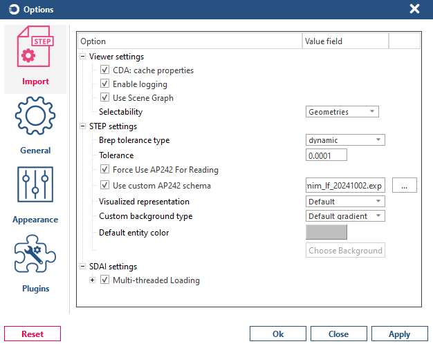
B-Rep Tolerance
The B-Rep tolerance controls the detail of rendered objects and can be either dynamic or static. This option controls how advanced B-Reps (objects that are drawn as-is, i.e., non-faceted bodies are created for these objects) deviate from original NURBS or analytical surfaces. Lower tolerance values produce a more visually correct result but increase the load time of a file.
Export a File
To export an open file to PDF format, choose File > Publish PDF. The next example shows how to export a scene to a PDF file and view it with Adobe® Acrobat® Reader®.
Append a File
To append an existing file to the currently opened file, choose File > Append.
Write to a File
To write changes to an existing file, right-click of the root node displayed in Object Explorer and choose Write in File. The current state of the model can be written to a compressed STEP file format (.stepA or .stepZ).
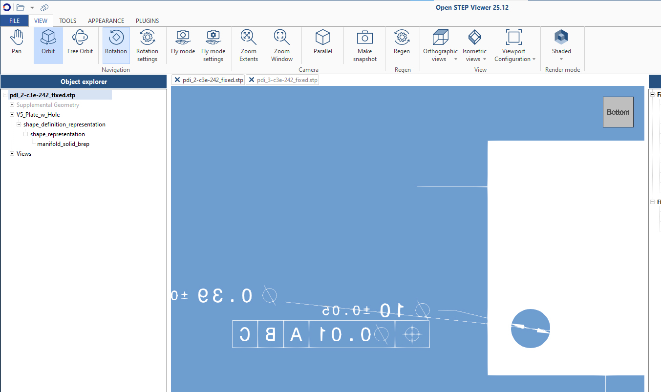
Explore Scene Objects
The Object Explorer panel allows you to explore objects of a 3D model. It displays the spatial structure of the currently opened model according to the ODA Common Data Access (CDA) interface. Click an object in Object Explorer to see its corresponding properties in the Properties panel on the right side. The Object Explorer panel allows you to explore objects of a 3D model. It displays the spatial structure of the currently opened model according to the ODA Common Data Access (CDA) interface. Click an object in Object Explorer to see its corresponding properties in the Properties panel on the right side.
The Options dialog allows you to modify the CDA: Cache Properties setting. This setting specifies whether to store native properties to CDA (Common Data Access) nodes during the import process. When using this option, you may see additional properties in the Properties panel, but note that they increase import time.

Also, you can right-click the Object Explorer panel to get various statistics about:
- Model objects — statistics for objects in the model
- Open time — time spent on various steps for loading a STEP file, creating geometry, displaying geometry, etc.
- Geometry-related information — information from Visualize SDK about quantitative characteristics of the geometric representation of the model, for example, count of edges, count of faces, number of shells, etc.
Additionally, when clicking a root node in Object Explorer, the Properties panel displays general details, including information from the header section and data section, for example, schema, authors, units, etc.
Also, some nodes with geometric representation in Object Explorer can be exported to an STL file using the Export to STL command.
You can use the Set Camera View command for nodes that have a corresponding view defined in a draughting model. This command sets a view for the camera of the specified node and disables the display of dimensions that do not exist in that model. To revert the camera parameters, use the Revert Camera View command.
For a product instance, you can get a list of user-defined properties if there are any attached. These properties can be exported to a CSV file.
You can hide, isolate, and unhide most nodes in Object Explorer. For more details, see the Hide, Isolate, and Unisolate Scene Objects section.
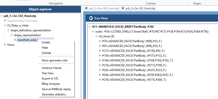
Tree View
A tree view provides an easy way of navigating a model in a tree-like manner from the specified node inside Object Explorer. Tree views are available for most nodes — right-click a node and choose Tree View.
Once a Tree View window is open, it displays a line from the STEP file that corresponds to the current node. A root node inside a tree view expands and shows its attributes where explicit attributes display in a regular font and inverse attributes display in italic font. These attributes expand and show other attributes or definitions with their attributes that can also expand and show their corresponding attributes, and so on.
The Tree View can also show subtrees for multi-dimensional aggregations.
Right-click in a Tree View window to choose how to navigate a file:
-
Search — searches for a line of the specified handle
-
Find by isInstanceOf/Find by isKindOf — performs a search inside a model for definitions of a specific instantiable type (isInstanceOf) or a specific type in general (isKindOf, which finds instances of derived types)
-
Find all users — searches for all objects that reference the specified line
-
Find users by role — searches for all objects that reference the specified line from a specific attribute
-
Set as root — sets the specified node as the root node in the current Tree View window
-
Get instance path — gets a path from the specified instance to the root node. The displayed path is copiable
-
Collapse all — collapses lower-level subnodes of attributes for the specified node
-
Open in new window — creates a new Tree View window for the specified node
-
Instance Viewer — opens the Instance Viewer window, which presents an alternate way to explore instances and their attributes (see View Object Instances next)
View Object Instances
Another way to explore scene objects is by using the Instance Viewer. In Object Explorer (or Tree View), right-click an object and choose Instance Viewer, which shows the selected instance with its entity definition hierarchy as it is defined within the EXPRESS schema and all assigned attribute values.
Also, the Instance Viewer provides performs SDAI-level validations/validation tasks on the current instance. Validation-related options are:
- Validate where rules
- Validate aggr size
- Validate aggr uniqueness
- Validate array not optional
- Validate binary width
- Validate inverse attributes
- Validate explicit attribute references
- Validate required explicit attributes
- Validate string width
- Clear validation results
Attributes are marked red if the validations fail. The next example shows validations that fail and one where validation is completed successfully and no attributes are marked red.
Highlight Scene Objects
You can highlight items that belong to an entity or highlight an entity itself. This means you can highlight two types of graphical data — entities and geometry. Highlighting can be done in three ways:
- Single-click — left-click directly on an object to highlight it
- First-click + second-click to the left — define a crossing window that crosses all objects to be highlighted. Objects that fit in or cross the area are highlighted
- First-click + second-click to the right — define a regular window that fits all objects to be highlighted. The objects that fit entirely in the area are highlighted
In the second and third case, the first click should not be on an object, otherwise the first case is activated, and the object is selected and highlighted. The simplest way to highlight is to directly click an entity. You can select multiple entities by pressing Ctrl and clicking them. Highlighted objects are selected in the Object Explorer panel.
By default, only entities are selected and, therefore, highlighted. To select and highlight geometry objects (for example shells), right-click the scene, then choose Selection Level > Geometry. The example below illustrates the difference between selection levels when clicking the same area in a model.
The next example shows highlighted entity objects with a crossing window. To make a crossing window, click anywhere in the scene where no object is located, then click again anywhere to the left of the first click.
The other option is to use a regular window for selection and highlighting. This way, the only objects that are highlighted are those that fit entirely in the window. To use this mode, click anywhere in the scene where no object is located, then click again anywhere to the left of the first click.
You can also highlight objects by hovering over them with the mouse. To turn on this feature, right-click the scene and check Highlight while Hover. The highlight color and modes can be customized by choosing File > Options > Appearance.
Hide, Isolate, and Unisolate Scene Objects
You can hide or isolate various graphical objects by selecting items in a viewport or in the Object Explorer panel. After the required objects are selected (and therefore highlighted), right-click and choose Hide or Isolate. To return to the initial state, use the Unisolate command.
The next example demonstrates using the Hide, Isolate, and Unisolate commands:
Note
The Back Face Culling visualization option affects the display of back faces that can be important when using the Hide command.
Scene Lighting
A rendered scene can have default or user-defined light sources. Because supported 3D file formats don't contain separate lights, default lighting is used for rendering. Different than standard lights, default lights rotate together with a camera, allowing an object to be illuminated from each side. The lighting direction of default lights is defined in the eye coordinate system (not the World Coordinate System).
To change lighting settings, choose Appearance > Light Settings.

The Default Lighting Parameters dialog opens.

Lighting Type
Lighting type option determines which type of light will be used for scene lighting. There are four types of lighting: one light, two lights, back light and user defined.
One light
A single light source is used to illuminate the scene. This can create a simple and focused lighting effect. Result of applying this option:

Two lights
Two lights are used for scene illumination. The model appears with two rays of lights and a reduced dark area. Result of applying this option:

Back light
The scene uses two lights but with a different placement. Result of applying this option:

User-defined
You can control the direction of the light source. The vector for the direction uses the eye coordinate system, not the World Coordinate System. The following images show several examples for setting up this light. Direction is (0, 0, 1):

In the previous case, the XY plane with the Z-direction extends from a viewer. The light source is behind the model, so if you change the direction of the light to (0, 0, -1):

One more example of custom light direction (0, -1, 0):

Light Intensity
Light intensity is the strength or amount of light produced by a specific light source. Large intensity values produce brighter light on objects in the scene. For example, lighting with the light intensity set to 0.5:

Light Color
Light sources can emit different colors. The light color is applied together with ambient color, object color, material's diffuse, and ambient colors to calculate the final color. The default light color is, white. Below is an example with the light color set to yellow:

And if the light color changes to blue:

Ambient Color
Ambient light color is the color of the background light in a scene. Ambient light is a type of indirect or global illumination that represents the light that is scattered and reflected from all directions, regardless of the presence or position of light sources. It provides a base level of illumination to all objects in the scene and helps prevent objects from appearing completely dark in areas where there is no direct light. For example, in the previous image where the light color is set to yellow, the ambient color is set to green. The global ambient light is scaled using the material's ambient property, which is orange in the following case.
In this light color example, when the light color is set to blue, the black area has green light when ambient light is added.

Available Tools
View tab
The View tab has the following options:

Navigation Group
The Navigation group provides tools that allow you to perform different operations with the camera, for example: pan, orbit, free orbit, and rotation of a view. Example of using tools from the Navigation group:
Camera Group
The Camera group provides tools that allow you to zoom to a window, zoom to extents (or press Ctrl + Backspace), set the projection of a camera, and get a snapshot of the active view. Example of using tools from the Camera group:
Also, you can make a snapshot of a current view with the Make Snapshot tool. Note that additional application elements such as WCS display, view cube, markups, FPS counter, etc. are saved in a snapshot.
Regen Group
The Regen group provides a tool that regenerates geometry data in the scene. Regeneration is a process that recalculates geometry for proper display on the screen. Regeneration can help save resources by reducing object detail when zoomed out in the current view when fewer details are needed. Likewise, regeneration can increase geometry detail after you zoom in to an object and if you see jagged edges. Regeneration is most relevant for curve, alignment, and boundary representation objects.
By default, Open STEP Viewer regenerates geometry automatically according to the camera distance. To regenerate geometry manually, click the Regen tool or press F5.
View Group
The View group has several predefined orthographic and isometric views for the camera and the ability to change the viewport configuration to single, two, or four viewports with different layouts. You can also make a viewport active and perform different operations in this viewport. Example of using tools from the View group:
Render Mode Group
The Render Mode group allows you to change the current visual style, for example to sketchy or hidden line. Examples of different visual styles:
Tools Tab
The Tools tab has the following options:

Markups Group
The Markups group provides tools for marking parts of a drawing, for example, render defects, building defects, collisions, key parts, etc. You can create markups from different shapes, free-hand sketches, and text notes, and you can save and load markups.

Note that markups are deleted when orbiting or rotating with the camera. To save a current view with markups, use the Save tool. Then you can load the view with all the markups when needed. Here is an example of how to use markups, save a view with markups, and load the saved view:
For component stamp markups, specify a property name in the first column to display the Display Name and Value columns.
Additionally, a work plane for markups can be modified. There are 3 options to set a work plane:
-
Default — sets a default work plane. The center of the coordinate system is the center of the current view, and the plane is aligned with the current viewing plane.
-
Set plane by normal to point — sets a work plane by specifying a normal to a point. You specify a point on a surface, and the normal is calculated automatically but can be modified manually. Note that for some markups it is important to specify a correct up-vector orientation, for example, for text markups
-
Set plane by three point — sets a work plane by specifying three points on a surface. The first point is the start of the coordinate system, the second point indicates the positive x- axis, and the third point indicates the positive y-axis. You can also manually specify the up- vector orientation of the work plane if necessary
Note
Markups are saved in snapshots that can be created by choosing View > Make Snapshots.
For more information, see Camera Group.
Measurement Group
The Measurement group contains tools for measuring distances. Distances can be measured between arbitrary points of a model's geometry or between points that strictly snap to vertices of a model. The measurement options allow you to select the color of visual elements used for measurements, snap point size, and measurement units. You can conduct multiple measurements with the same distance measurement type (arbitrary or snapping to vertices). Example of using measurement tools:
Note
While using measurement tools, all basic camera management options are available via the mouse wheel. To move the camera, hold down the mouse wheel and move the mouse. To rotate the camera, press Shift while holding down the mouse wheel and move the mouse.
Sectioning Group
The Sectioning group contains tools for working with cutting planes, which are planes that visually cut the geometry of a model. You can show or hide cutting planes, add a cutting plane using the x-, y-, or z-axis, and clear cutting planes. With the Fill tool you can enable or disable a section fill and also specify a fill color and pattern. Cutting planes can be repositioned around the scene. To move or rotate a cutting plane, click it, and drag the highlighted tools.
Collisions Group
The Collisions group contains two collision detection tools. The Collide tool detects collisions between geometric objects and entities in real time. The Collision Detection tool shows all collisions between selected objects. For example, you can use collision detection to check whether geometric objects are aligned properly and do not intersect each other.
To interactively detect collisions:
- Click the Collide tool
- Click an entity to define the input set. Press Ctrl while clicking to select multiple entities
- Press Enter. The input set is collided with all other model objects
- Check the selected objects for collisions with other objects. Drag the coordinate system handles by the x-, y-, and z-axes to detect collisions. Collided objects are highlighted
- When done, press Esc
To show all collisions between selected objects:
- Click the Collision Detection tool
- In the Collisions panel, specify the collision options: type, tolerance, distance, and choose objects for detecting collisions or all collisions
- Collisions are displayed in the Collision Results list. Double-click any item in the list to render a corresponding collision in the scene
- (Optional) Save selected collisions or all detected collisions to the BCF format
- When done, click Close
Note
Collision detection does not apply to helper objects that are not part of the model (annotations, text, dimension objects, referencet objects, etc.).
Explode Group
The Explode group contains a tool for simulating an explosion of all geometry components of a model. When working with the Explode tool, use the slider to control how much the model's elements are scattered as a result of the explosion.

Appearance Tab
The Appearance tab has the following options:

Appearance Group
The Appearance group allows you to turn on or off the display of World Coordinate System (WCS) axes, change light settings, and change the background color to custom or default gradient. Example of using tools from the Appearance group:
Visual Effects Group
The Visual Effects group allows you to enable anti-aliasing for smoother graphics display and to cast a ground shadow under the model. Example of enabling and disabling the anti-aliasing and ground shadow effects:
Panels Group
The Panels group allows you to show or hide the Object Explorer and Properties panels. Example of hiding and showing the Object Explorer and Properties panels:
Plugins Tab
The Plugins tab has the following options:

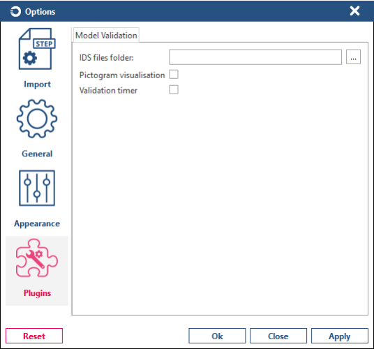
Model Validation
The Model Validation plugin checks that the model meets requirements for the exchange of CAD data. The validation engine performs SDAI-level validations, checking whether a model is correctly composed from the perspective of SDAI.The Model Validation plugin checks that the model meets requirements for the exchange of CAD data. The validation engine performs SDAI-level validations, checking whether a model is correctly composed from the perspective of SDAI.

In the plugin window, choose the required validations and then click Validate to start validation tool. When the process is finished, a new dialog displays the validation results, which can be filtered and saved in text or HTML format.
Layers Manager Plugin
The Layers Manager plugin allows you to view and manage properties of existing layers. Available layer properties that can be changed:
- Name
- Visibility
- Color
- Line type
- Line weight
- Description
- Identifier
Below you can see a layer manager that displays a layer (can be multiple layers in other files) and its properties.

After changing visibility of the layer:

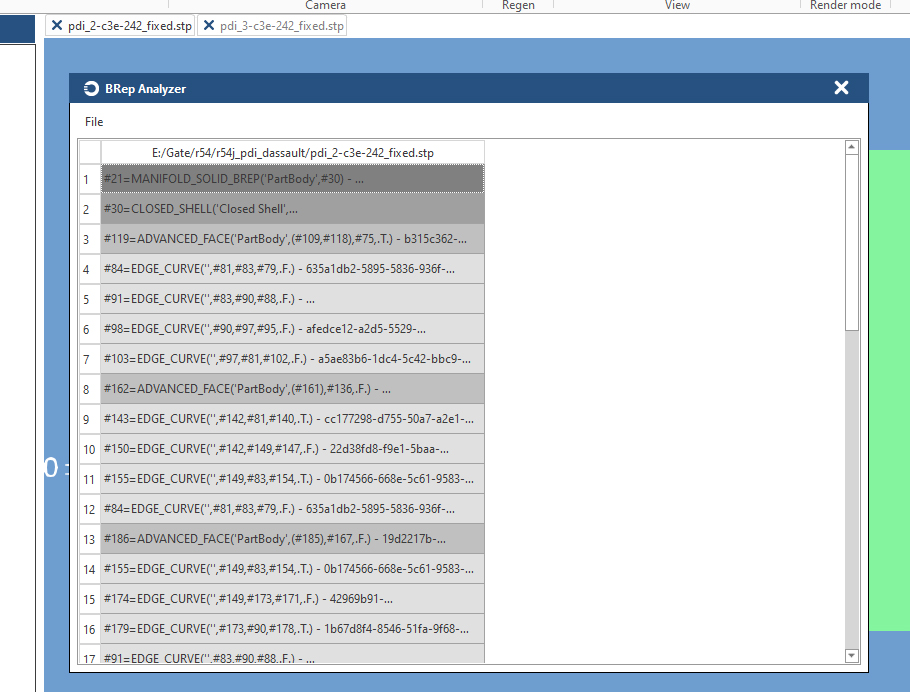
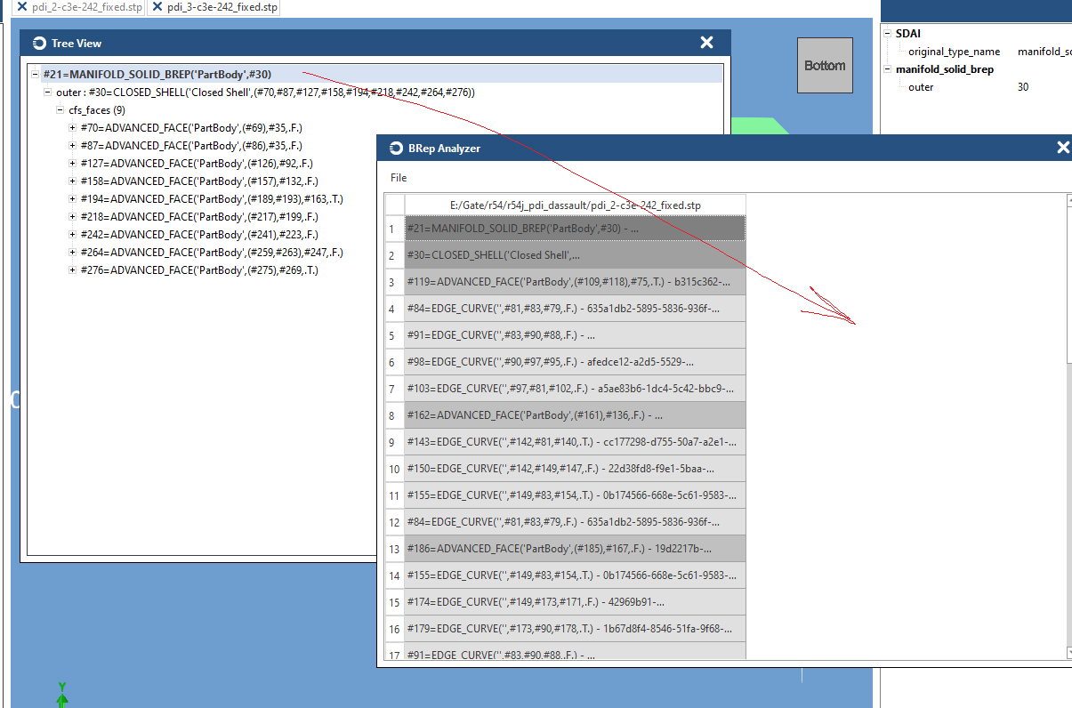
B-Rep Analyzer
The B-Rep Analyzer plugin allows you to open a separate window for a manifold_solid_brep entity and get detailed information about topological information of the instance and other data. It also provides a feature of opening multiple instances in the window so they can be compared. The plugin is available only for files of STEP AP242 schemas with UUID attributes support (dev. versions), if appropriate data is stored in STEP file.
- Make sure that the CDA: Cache Properties setting is enabled.
- Choose File > Open and select STEP files to compare.
- Choose one of the following options:
- Right click on manifold_solid_brep into Object Explorer tree, popup menu with BRep Analyzer line will appear. Click on BRep Analyzer to open the plugin.
- Choose Plugins > Brep Analyzer to open an empty plugin window, then drag and drop the manifold_solid_brep node from Object Explorer to the Brep Analyzer window.
- Choose Plugins > Brep Analyzer to open an empty plugin window, open Tree View, search for a manifold_solid_brep instance, drag and drop it to the Brep Analyzer window.
- At this step the Brep Analyzer displays B-Rep data of the needed manifold_solid_brep instance
- For second file, use one of the options from above (a, b or c) to open the manifold_solid_brep in the same plugins window. For example, find manifold_solid_brep in Object Explorer, and call Tree View plugin from popup menu on right click.
- Drag and drop MANIFOLD_SOLID_BREP line into BRep Analyzer.
- New column with unfolded BRep topological elements will appear.
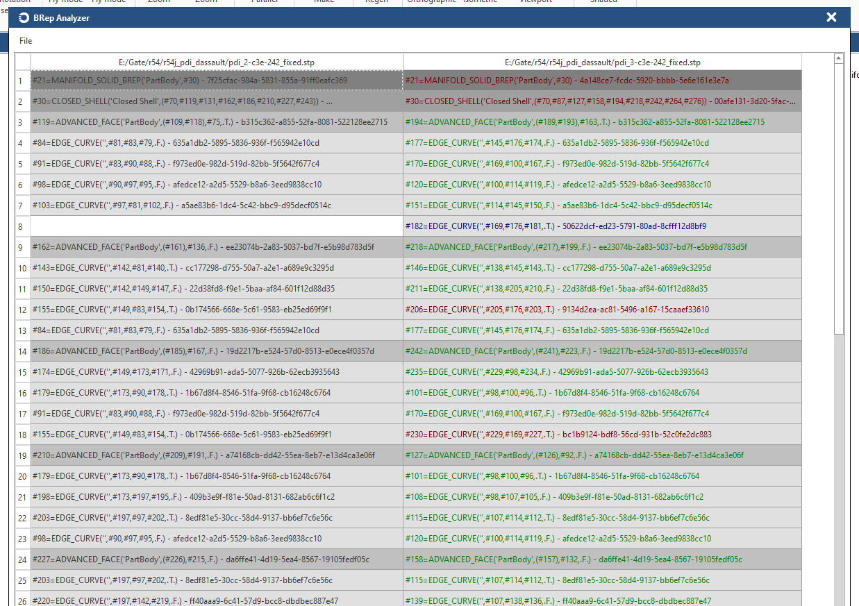


Also, with File > Clear you can clear data from the plugin's window, and with File > Export to CSV you can export the data to CSV format.
Customize Viewer Options
Choose File > Options to configure Open STEP Viewer according to your needs.
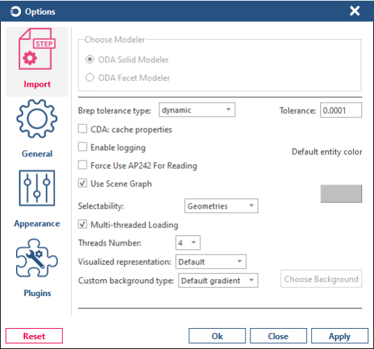
-
Import options allow you to specify the modeler settings, multi-threaded loading, scene graph, selectability, and other options that are used during import
-
General options allow you to set up the display, visualization, render, regeneration, and other general application options

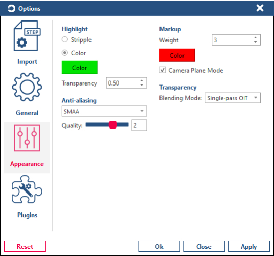
-
Appearance options are used to set up highlight, markup, anti-aliasing, and transparency options
-
Plugin options are used to set up working with supported plugins


About Open STEP Viewer
Choose File > About to get information about the current Open STEP Viewer application, including the current version, supported schemas, contacts, links, and other information.
